
ASSIGMENT - make something big
COMPUTER-CONTROLLED CUTTING {DESIGN OF PROJECT}
I have always loved making and restoring furniture, so this was a great opportunity to look at the design side of it, having the tools to make something more than single functioning.
I decided to look at what I need, I need a desk space a stepping stool and extra seating for guests. I decided I would attempt to combine all these elements into one multi-functional unit.
I started by designing the idea of the desk, looking at school desks and thinking of how to modify them.
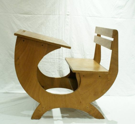
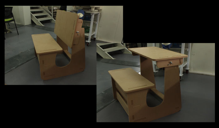
I wanted to get the top of the desk to fold down, and so reversed it could be used as a bench for two people to sit on. But it had to be low enough to also use as a step stool.
So I started by doing design drawings in illustrator. Just the general shape and looking at how this might possibly work. Rotation / height / width.
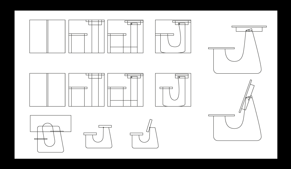
Checking the angles for rotation of the desk top, as well as taking into consideration ergonomics for comfortable seating.
Considering the low height of the seat (to make it functional as a step) I ensured that there was nothing in the way of knees or stretched legs, as well as giving slightly more height to the desktop, 250 instead of 200 mm, so that one can comfortably slide into the bench.
I made the seat 700 wide for two people to sit on if in bench position, and made the angle of the seat back 102 degrees, which should be ergonomically comfortable. I also added shelving in the seat bottom for storing paper work,
but more importantly to serve as structural strengthners between the two outer pieces making up the frame of the unit.
I added two more "bars" across the front for structural integrity. Trying to keep it as open as possible still for legs movement.
Then I made a scaled version on the laser cutter, to double check sizes.
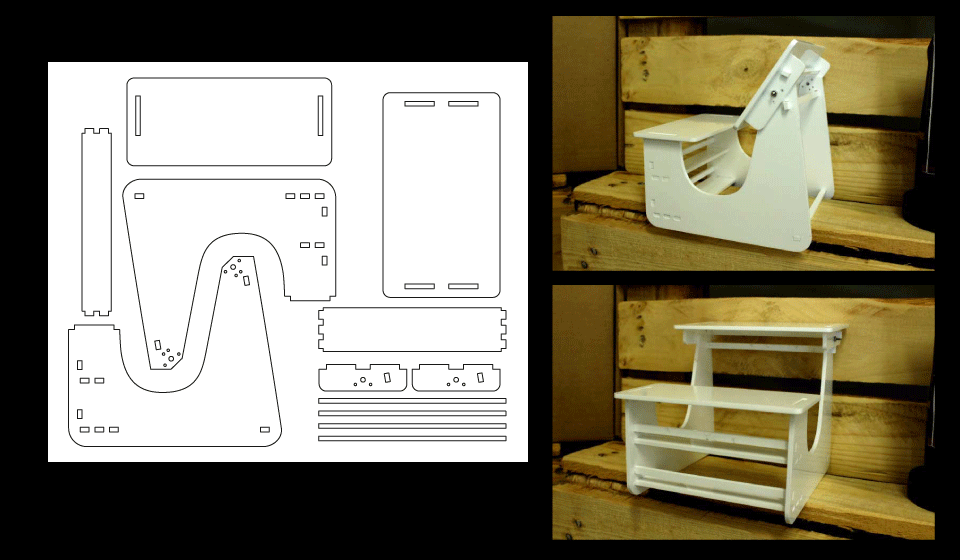
It came out really well, but I realised there were a few problems with the design and a few elements I had not considered.
I reworked the distance between the back rest and seat, when being used as a bench, this was too far apart in the original drawing. I also had not accounted for the distance on the outside of the table for fixing the table top to the bench. I adjusted this as well.
I also was informed that the shopbot might not take kindly to smaller cuts and so made longer slots and inserts instead of multiple smaller ones.
This also went for the struts which I added an insert too.
Kirstin cut her designs first and we realised the material was quite a bit bigger, reading between 16.4 and 16.8 mm, so we adjusted our artwork.
Where I had set my cuts for 16.3mm to snap fit I went up to 17.3mm to account for the fluctuation in size, as well as making the widths 1mm bigger.
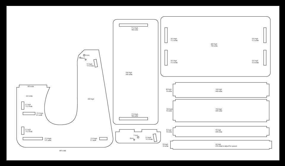
I added my sizes and finalised the shapes. I then combined the shapes to make solids.
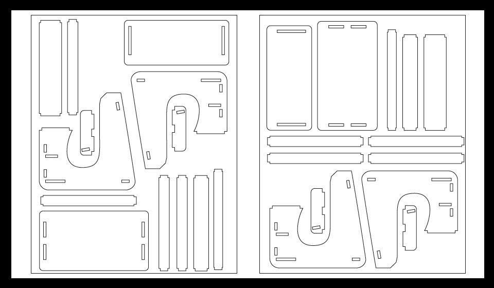
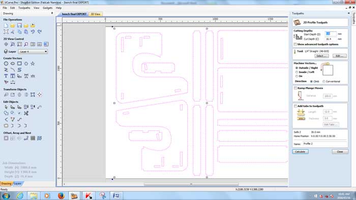
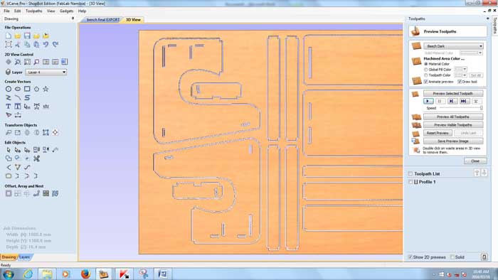
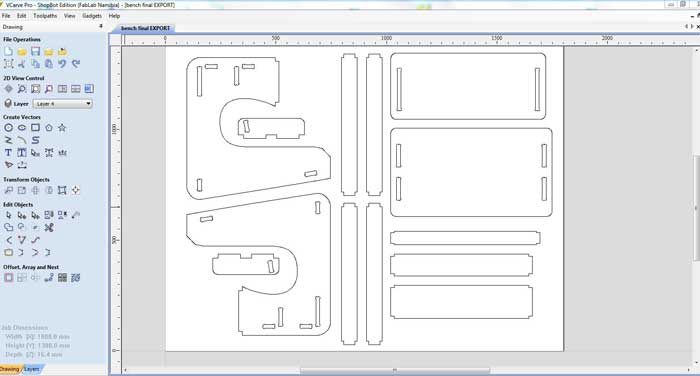
I then looked at the nesting, better use of space, materials, cutting time, costs. I exported the file as a DXF and imported into RHINO to check that there were no double lines. After that I saved the file as a DXF again and imported it into VCARVE PRO.
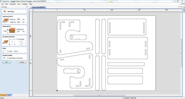
I set up the file by first setting the material size (1800mm x 1380mm), depth (16.4mm)and orientation. We did not use an off-set path.
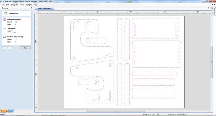
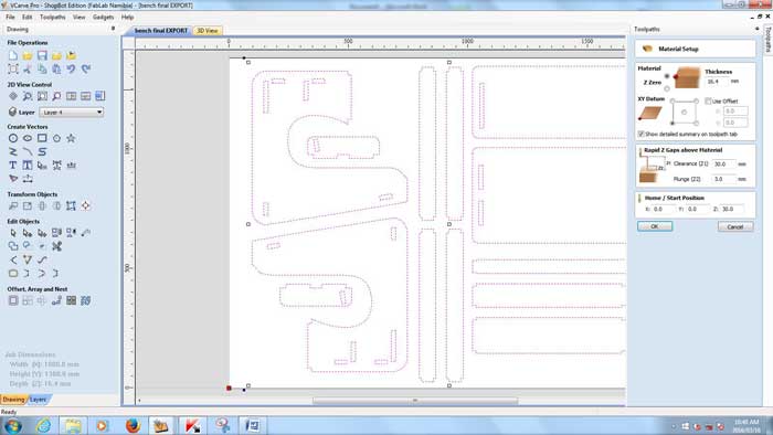
I ensured there were no open paths, using the join tool. I didn't and so I centered my artwork on the material and moved onto setting the toolpaths and the cutting bit size. In our case 6mm.
In the settings also set the plunge amount to 3, and the z jump setting to 30mm to avoid cut pieces that jump out of the wood.
Set wether you are doing an inside cut or an outside cut. This would be according to what you had set your file up as, in my case outside.
I saved the artwork.
From there we did a lesson on the SHOPBOT.
1. Heat the spindle by typing in c5 in th coding section and hit the green button on the control, once the spindle is running smmothly hit enter. Allow the spindle to run for approximately 20min, to allow it to be heated properly.
2. Place the wood on the bed, and level agains one of the edges, look for the straightest and even ones. Drill holes and screws into the four corners to keep in place.
3. Zero the bed. Move the spindle forward and to the right corner, where you want it to read zero. You move the spindle by using the arrow keys on the keyboard. Lower the the spindle to where it touches the top of the wood, this is to set you z to 0.
(If you need to change the bit unlock the machine using the key, this switches the spindle off. Move the plastic cover by unscrewing the back screw, and lift it away from the bit. Use the wrench attached and a spanner to loosen the collet and drill bit. When reattaching allow the thread on the collet to do most of the work when screwing back on as the thread is very important and forcing it will cause damage. Replace the plastic cover and screw tight. insert key and lock the machine to activate the spindle.)
In the SHOPBOT control software open the small gameboy looking icon, to set your machine to the zeros you have physically set.
Click on the zero button, check x,y,z-axis and set to zero.
4. Switch on the extractor.
5. Open the artwork. You can now start printing.
NOT COMPUTER-CONTROLLED CUTTING
{JIGSAW}
I had to jigsaw the edges of my final pices to make them straight for the snap fit to work.
{DRILLING}
I printed out scaled versions of my artwork so as to drill the holes for the rods, so that the table can flip.
I wanted to use dowel sticks and try not use screws but again it was pointed out to me that the dowel sticks might not be strong enough.
I used a 11mm bit on the bench press drill for the main rotational function and an 8mm bit in the hand drill for the placement keeper.
{HAMMERING}
I assembled and hammered the pieces together the fit is quite tight and strong.
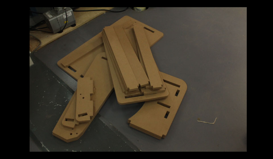
Unfortunately I did not take any photos of the actual milling process. I was so overwhelmed by the intensity of the machine and trying (hoping) not to break anything, to remember to push the right button if anything does go wrong, that I completely blanked out on that.
{NOTES}
I did not reset the depth of my insert pieces, for next time I will remember to do that, I left them set at 16mm, which is what we originally thought the depth of the material was. So my fits are not exact.
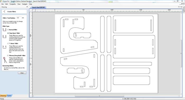
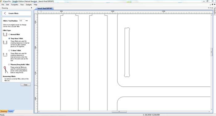
{FIXED FILES}
Ohad met with me and explained that what I should have done is make a dog bone fit in the corners for my files, rather than jig sawing the edges straight.
I opened my artwork in Vcarve and added the dog bone fillets.
If time permits I will possibly look at remaking my desk. But I will keep the file and lessons learnt for future reference.
Download my working files HERE